Table of Contents
Target Audience
This article assumes that the reader is familiar with basic electronics circuits and terminology.
Introduction
The purpose of this article is to familiarize the reader with the basics of the I2C communications bus, including how it is set up, its physical properties, and where and why it is often used.
What Is I2C?
I2C is ordinarily pronounced “I-two-C”, though it is also sometimes written as IIC (and pronounced “I-I-C”) or I2C (pronounced “I-squared-C”). The acronym stands for Inter-Integrated-Circuit. It is a type of serial computer bus and communications protocol that was first introduced to the market by Philips Semiconductor in 1982.
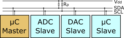
I2C is a way of allowing multiple electronic devices (most often low-speed, peripheral integrated circuits) to communicate with each other over a single pair of wires. These wires are also called data lines, or buses. The first of these buses is the data line and is called the SDA (Serial DAta) line, and the other bus is the clock, or SCL (Serial CLock) line. Since all devices on any I2C circuit are hooked to these two lines to communicate, most I2C-compatible devices have pins labeled SDA and SCL, as well as VIN and GND pins for positive and ground connections.
How Does I2C Work?
Both the clock and data buses are open-drain lines. A resistor must be connected between each line and the circuit’s positive voltage supply (also referred to as Vcc) in order for the bus to work correctly. The size of these resistors can vary, from 1 kΩ all the way up to 47 kΩ, but they must be present between the bus and the system’s HIGH voltage. If they are not present, all lines will be pulled low, and the I2C bus will fail to work. Luckily, only one pair of resistors (one for each line) is necessary for the entire system, not a pair for each device–that could quickly get messy with a lot of devices.
Attaching Devices
Quite a few devices (also called nodes) can be attached to these buses. In fact, the number of devices that can practically be connected to any I2C circuit is normally limited only by space, the inherent capacitance of the lines, and the addresses of the connected devices. Most experts agree that this limit falls around 1008 devices.
Types of Devices in I2C Communications
There are two kinds of devices in I2C communications: masters and slaves. In most implementations of the protocol there is one master device connected to many slaves. It is possible to have more than one master communicating with various slave devices as well as other masters, but this form is less common and is a bit beyond the scope of this introduction. Many I2C devices can be configured as either a master or a slave, depending on the desired system results. The master node is the one device that controls the clock (SCL) line, and is the only device that can initiate a data transfer. The slave nodes are limited to listening for and responding to calls from the master node. Each node, including the master, has a unique (normally 7-bit) address that identifies it on the I2C network. In some cases the address can be 10 bits in length, allowing for more than 128 different devices, but this is not a normal setup.
During the operation of an I2C system, the master node sends commands and requests on the data line. These signals are 8 bits in length, are only begun when the clock line is HIGH, and are started with a particular ‘start’ sequence and finished with a particular ‘stop’ sequence. The start sequence alerts all connected slave nodes that a data transfer request is imminent. The next sequence the master sends out is the address of the slave with which it wants to communicate. The named slave node then responds to the master, beginning at the next HIGH clock signal, and the other slaves go back to listening for their address to be called.
The eighth bit that is sent with the command, after the 7-bit device address, is a simple read/write bit. It tells the addressed device whether the master device will be reading from or writing to it. This allows the receiving device to either prepare data to send or prepare to receive data along the SDA line at the next clock HIGH signal.
Clock Speed
The clock speed (and the associated signal transfers) on most I2C circuits normally falls somewhere between serial communications and SPI speeds, between 100kHz and 400kHz. I2C is commonly used in systems where simplicity, low cost, and low power are more important than speed. Some of these applications include analog-to-digital converters, LCD displays, real-time clocks, and many different sensors such as barometers, compasses, and even GPS receivers.
I2C Applications
I2C is a very useful communications protocol, though it may only be applicable to a small number of applications. It is ideal for small, low-power-consumption settings, and as a result has found a following among many hobbyists, who use it to interface sensors and controls with embedded devices and microcontrollers such as the Arduino and the Raspberry Pi. Two of the Pi’s GPIO pins are preset to interface with devices using the protocol, and the Arduino wire library allows communications with I2C devices. Learning and using I2C can significantly extend a hobbyist’s toolkit when it comes to building projects.
About Atlantic.Net
Atlantic.Net offers VPS hosting as well as managed hosting services which include a layer of business-essential managed services to your hosting packages. Contact us today for more information.